


초음파 센서로 거리 측정하기
[컴퓨터월드] 아두이노는 이탈리어로 ‘친한 친구’라는 뜻을 가진 대표적인 오픈소스 하드웨어다. 딱딱하고 접근하기 힘들었던 임베디드 분야를 누구나 쉽게 접근할 수 있도록 만든 미니 기판이라 할 수 있다. 이번 강좌에 사용하는 아두이노 오렌지보드는 한국형 아두이노라 할 수 있다.
아두이노의 보급은 오픈소스 하드웨어의 확산을 불러일으켰고 메이커 문화의 확산에도 큰 기여를 했다. 최근에는 인텔, 마이크로소프트 등 대형 기업들도 이런 오픈소스 하드웨어시장에 뛰어들기 시작했다. 그 만큼 오픈소스 하드웨어 시장의 잠재력이 커졌다는 얘기이다.
초음파 센서란 무엇인가?
인간이 들을 수 있는 영역 (가청영역) 은 약 20~20KHz이며, 이것보다 주파수가 더 높은 음을 초음파 (Ultrasonic)라고 한다. 개인적인 차이가 있으나, 일반적인 성인은 20KHz 이상의 높은 소리는 듣지 못 한다.
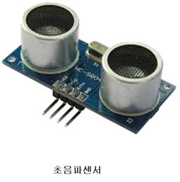
초음파 센서는 사람의 귀에 들리지 않을 정도로 높은 주파수(약 20KHz 이상)의 소리인 초음파가 가지고 있는 특성을 이용한 센서이다. 초음파는 공기나 액체, 고체 모든 상태에서 사용할 수 있다. 파장이 10㎝~수㎛밖에 되지 않기 때문에 공기 속에서는 곧 감쇠되지만 물이나 기름 속에서는 멀리 전파하고 지향성이 날카롭다. 강력한 초음파를 내어도 귀에 장해를 주지 않기 때문에 여러 방면에서 이용하고 있다.
이 예제에서 사용된 초음파 센서는 약 40KHz 정도의 주파수를 생성하여, 5~7m정도까지의 거리를 측정할 수 있다.
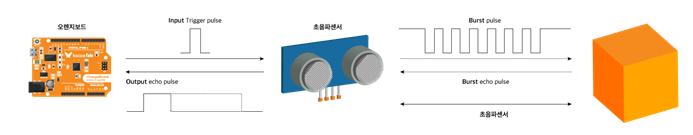
거리측정을 위한 초음파 센서는 송신부와 수신부로 나뉘어져 있으며, 송신부에서 일정한 시간의 간격을 둔 짧은 초음파 펄스를 방사하고, 대상물에 부딪혀 돌아온 에코 신호를 수신부에서 받아 이에 대한 시간차를 기반으로 거리를 산출한다. 이를 통해 장애물의 유무, 물체의 거리 또는 속도 등을 측정할 수 있다.
초음파를 발생시키는 원리는 피에조 부저에서 소리를 나게 하는 피에조 효과(압전효과)와 같다.
초음파 센서 사용방법
초음파 센서의 송신부(Trig)에서 일정한 시간의 간격을 둔 짧은 초음파 펄스를 방사하고, 대상물에 부딪혀 돌아온 에코 신호를 수신부(Echo)에서 받아 이에 대한 시간차를 기반으로 거리를 산출한다.
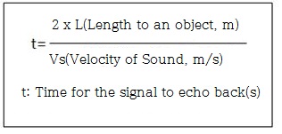
1cm를 이동하는데 걸리는 시간은 다음과 같이 구할 수 있다.
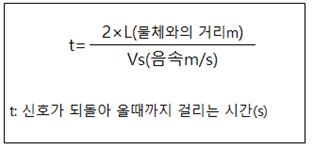
따라서, t = 2 * 0.01 / 340 = 58.824µs 로, 초음파가 1cm를 이동하는데 걸리는 시간은 약 29µs가 걸리며, 초음파가 반사된 물체와의 거리는 다음과 같이 구할 수 있다.
|
거리(cm) = duration (왕복에 걸린시간) / 29 / 2 (왕복) |
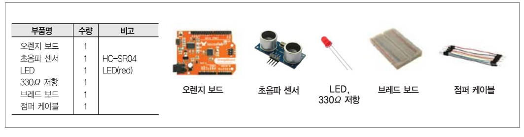
필요한 부품 목록
오렌지보드로 거리를 측정해보기 위한 준비물은 아래와 같다.
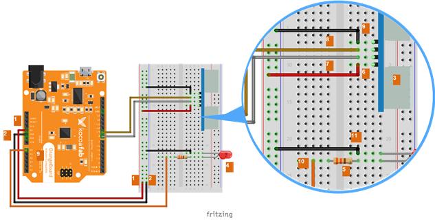
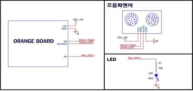
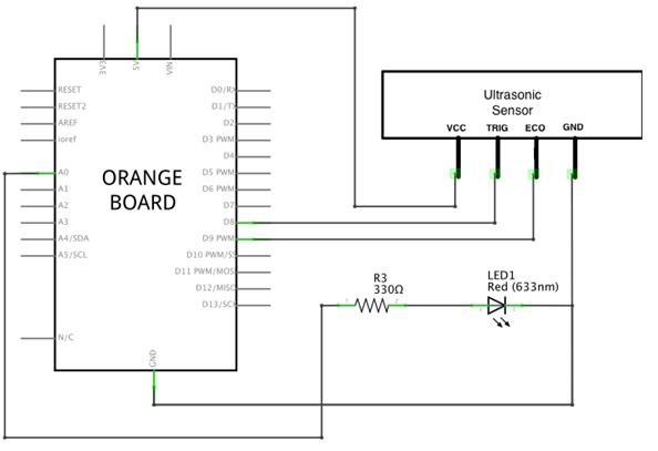
하드웨어 연결하기
릴레이와 트랜지스터, LED는 오렌지보드 핀 번호 연결 그림과 같이 연결한다.
1. 오렌지보드의 5V핀을 브레드보드의 +버스에 연결한다.
2. 오렌지보드의 GND핀을 브레드보드의 -버스에 연결한다.
3. 초음파센서를 그림과 같이 세로로 꽂는다.
4. LED를 애노드(긴 단자)가 아래쪽으로 향하게 하여 꽂는다.
5. LED의 애노드에 330Ω 저항을 연결한다.
6. 초음파센서의 Vcc단자를 +버스에 연결한다.
7. 초음파센서의 Trig단자를 오렌지보드 8번핀에 연결한다.
8. 초음파센서의 Echo단자를 오렌지보드 9번핀에 연결한다.
9. 초음파센서의 Gnd단자를 -버스에 연결한다.
10. LED 애노드와 연결된 저항을 오렌지보드 A0번핀에 연결한다.
11. LED 캐소드(짧은)를 -버스에 연결한다
소스코드
| /* 제목 : 초음파센서로 거리 측정하기 내용 : 초음파센서로부터 10cm 이내로 물체가 감지되었을때 LED가 켜지도록 만들어 봅시다. */ // 초음파센서의 송신부를 8번핀으로 설정합니다. int trig = 8; // 초음파센서의 수신부를 9번핀으로 설정합니다. int echo = 9; // LED를 A0핀으로 설정합니다. int led = A0; // 실행시 가장 먼저 호출되는 함수이며, 최초 1회만 실행됩니다. // 변수를 선언하거나 초기화를 위한 코드를 포함합니다. void setup() { // 초음파센서의 동작 상태를 확인하기 위하여 시리얼 통신을 설정합니다. (전송속도 9600bps) // 메뉴 Tool -> Serial Monitor 클릭 Serial.begin(9600); // 초음파센서의 송신부로 연결된 핀을 OUTPUT으로 설정합니다. pinMode(trig, OUTPUT); // 초음파센서의 수신부로 연결된 핀을 INPUT으로 설정합니다. pinMode(echo, INPUT); // LED가 연결된 핀을 OUTPUT으로 설정합니다. pinMode(led, OUTPUT); }// setup() 함수가 호출된 이후, loop() 함수가 호출되며, // 블록 안의 코드를 무한히 반복 실행됩니다. void loop() { // 초음파 센서는 송신부와 수신부로 나뉘어 있으며, // 송신부터 수신까지의 시간을 기준으로 거리를 측정합니다. // 트리거로 연결된 핀이 송신부를 담당하며, 에코로 연결된 핀이 수신부를 담당합니다. // 송신부에서 2마이크로초 정도 또는 그 이상의 시간동안 초음파를 발생시킵니다. // 초음파 발생 전후로, 잡음을 제거하기 위하여 전류를 보내지 않도록 설정합니다. digitalWrite(trig, LOW); digitalWrite(echo, LOW); delayMicroseconds(2); digitalWrite(trig, HIGH); delayMicroseconds(10); digitalWrite(trig, LOW); // 수신부의 초기 로직레벨을 HIGH로 설정하고, 반사된 초음파에 의하여 LOW 레벨로 바뀌기 전까지의 시간을 측정합니다. // 단위는 마이크로 초입니다. unsigned long duration = pulseIn(echo, HIGH); // 초음파의 속도는 초당 340미터를 이동하거나, 29마이크로초 당 1센치를 이동합니다. // 따라서, 초음파의 이동 거리 = duration(왕복에 걸린시간) / 29 / 2 입니다. float distance = duration / 29.0 / 2.0; // 측정된 거리 값를 시리얼 모니터에 출력합니다. Serial.print(distance); Serial.println("cm"); // 측정된 거리가 10cm 이하라면, 아래의 블록을 실행합니다. if (distance < 10) { // LED가 연결된 핀의 로직레벨을 HIGH (5V)로 설정하여, LED가 켜지도록 합니다. digitalWrite(led, HIGH); } // 측정된 거리가 10cm 이상이라면, 아래의 블록을 실행합니다. else { // LED가 연결된 핀의 로직레벨을 LOW (0V)로 설정하여, LED가 꺼지도록 합니다. digitalWrite(led, LOW); } // 0.2초 동안 대기합니다. delay(200); } |
초음파 센서는 LCD와 달리 별도의 라이브러리(센서를 작동시키기 위해 필요한 변수나 함수를 모아놓은 파일)가 필요 없다. 초음파 핀에는 총 4개의 핀이 있는데 2개는 전원 공급을 위한 VCC(+)핀과 GND(-)핀이고 나머지 두 개의 핀이 Trigger핀과 Echo핀이다. Trig핀은 말 그대로 초음파를 발생시키는 역할을 하며 Echo핀은 발생된 초음파가 어떤 물체에 반사되어 되돌아 올 때 그 초음파를 수신하는 역할을 한다.
그렇기 때문에 Trig핀은 초음파를 외부로 발생시키므로 핀을 OUTPUT으로 설정하고 Echo핀은 외부의 초음파를 수신하는 역할을 하기 때문에 핀을 INPUT으로 설정한다.loop()안에 있는 코드 중 아래의 코드는 초음파를 발생시키기 전 Trig핀과 Echo핀의 상태를 세팅하는데 쓰인다. 처음에는 두 핀 모두 LOW로 세팅하여 어떠한 파장도 발생되지 않고 잡음도 없게 만든다.
그리고 나서 2마이크로초 뒤에 Trig핀에 HIGH신호를 발생시켜 초음파를 생성한다. 이 초음파는 10마이크로초 뒤에 Trig핀이 LOW가 될 때까지 지속된다.
| digitalWrite(trig, LOW); digitalWrite(echo, LOW); delayMicroseconds(2); digitalWrite(trig, HIGH); delayMicroseconds(10); digitalWrite(trig, LOW); |
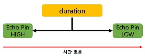
아래 PulseIn함수는 아두이노IDE에서 별도로 정의되 있는 함수로, 지정된 핀이 매개변수 안의 상태를 가질 때부터 시간을 재기 시작하여 상태가 바뀌면 시간 측정을 중지하여 상태가 바뀌기 전까지의 시간을 측정하는 함수이다.
아래 코드로 예를 들면 Echo핀의 초기 상태를 HIGH로 만들고, 시간 측정을 시작하여 Echo핀에서 초음파를 수신하여 LOW로 바뀌기 전까지의 시간을 측정하게 된다.
| unsigned long duration = pulseIn(echo, HIGH); |
pulseIn함수를 통해 duration 변수에 저장된 값은 초음파가 초음파 센서를 출발해서 들어오기까지의 시간이다. 이 값을 거리로 바꿔주기 위해서는 위에서 설명한 공식에서 도출된 값을 계산해야 한다.
| // 초음파의 속도는 초당 340미터를 이동하거나, 29마이크로초 당 1센치를 이동합니다. // 따라서, 초음파의 이동 거리 = duration(왕복에 걸린시간) / 29 / 2 입니다. float distance = duration / 29.0 / 2.0; |
distance앞에 쓰여있는 float라는 값은 distance라는 변수의 타입을 정의할 때 쓰인다. float는 int와 달리 소수점을 표현하는 값을 저장할 때 선언된다. float 선언으로 인해 distance라는 변수는 소수점을 가진 값을 저장할 수 있게 된다. 위 공식을 통해 나온 값은 distance라는 변수에 저장되며 이 거리값은 if조건문을 통해 물체와의 거리가 10cm 이하로 측정될 경우에는 LED가 켜지게 만들고, 10cm 이상으로 측정될 경우에는 LED가 꺼지게 만든다.
마치며
초음파 센서는 특정 물체와의 거리 측정을 위해 쓰이는 센서이며, 아두이노 센서 중에서도 상당히 많이 쓰이는 센서이다. 사용법이 간단하기 때문에 다양한 프로젝트에서 응용되어 쓰이고 있다.
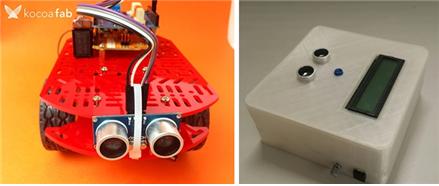
위와 같은 장애물을 감지하는 자율주행로봇이나 윗몸일으키기 카운터 장치도 간단히 만들어 볼 수 있고, 미니 레이더 장치를 만들어서 주변 물체와의 거리도 탐지해 볼 수 있다. 하지만 비교적 근거리는 잘 측정되지만 거리가 점점 멀어질수록 값이 부정확해지는 단점이 있다. 또 파장을 흡수할 수 있는 스폰지과 같은 흡음재 재질의 물체는 제대로 거리를 측정하지 못한다는 단점도 있다. 그래도 무난한 가격에 무난한 거리측정을 할 수 있는 센서를 원한다면 초음파 센서가 역시 좋은 센서가 아닌가 싶다.
프로젝트에 대해 더 자세한 내용을 알고 싶다면 Kocoafab.cc를 방문해 보길 바란다.
 코코아팹은 한국 메이커 문화를 만들어가는 온라인 메이커포털이다. 오픈소스 하드웨어 오렌지보드의 생산과 활용법 공개 등 많은 활동을 진행하고 있다. |
[Learning]
Easy-to-follow Orange Board Tutorial (5)
How to Measure a Distance Using an Ultrasonic Sensor
[Computerworld] Arduino means a close friend in Italian and is a typical open-source hardware. It is a mini board made for anyone to easily access an Embedded field, which has been hard and difficult to approach. The Arduino Orange Board to be used in this tutorial is a Korean version of Arduino boards.
The distribution of Arduino boards triggered the spread of Open Source Hardware (OSHW) and significantly contributed to the spread of Maker Culture as well. Recently, conglomerates such as Intel, and Microsoft, started entering this open-source hardware market. This reflects that the potential of open-source hardware market has grown likewise.
What is an Ultrasonic Sensor?
The range humans are capable of hearing(Hearing Range) is 20Hz~20KHz, and the sound that has a higher frequency than this is called ultrasound. Despite individuals’ differences, a normal adult is not able to hear sounds higher than 20KHz.
An ultrasonic sensor is a sensor utilizing properties of ultrasound, which has higher frequencies than audible to human ears(about 20KHz or higher). Ultrasound can be used in all medium states such as air, liquids, or solids.
Because its wavelength is only from 10cm to few μ, it quickly attenuates in air. But in water or oil, it can propagate farther exhibiting its sharp directivity. Because even intense ultrasounds are not harmful to human ears, it is used in many fields.
The ultrasonic sensor used in this example is capable of generating approximately 40 KHz frequencies and measuring distances reaching up to 5~7m.
An ultrasonic sensor to measure distances consists of a transmitter(Trig) and a receiver(Echo), and calculates the distance from the time difference between generating a short ultrasound pulse in regular time intervals and receiving its echo returning from an object reflected. By doing so, it can detect whether or not there is an obstacle as well as measuring the distance or speed of an object.
The principle of generating ultrasound is the same as the Piezo effect where sound is generated from a Piezo buzzer(Piezoelectric effect).
How to Use an Ultrasonic Sensor
The transmitter emits a short ultrasound pulse from the Trig in regular time intervals and the receiver receives its echo returning from an object. Then, the sensor calculates the distance from its time difference. The time elapsed to travel 1cm is as follows:
|
Distance(cm) = Duration (Round-Trip Time) / 29 / 2(Round Trips) |
List of Required Items
To measure distance by Orange Board, the following items are required for preparation.
How to Connect the Hardware
For relays, transistors, and the LED, connect the pin numbers of Orange Board as follows:
1. Connect 5V pin of Orange Board to + bus of Breadboard
2. Connect GND pin of Orange Board to - bus of Breadboard
3. Insert the Ultrasonic Sensor vertically having its + connector face upward as shown in the figure.
4. Insert the LED having its anode(long leg) facing downward
5. Connect the 330Ω Resistor to the anode of the LED.
6. Connect VCC connector of the Ultrasonic Sensor to + bus.
7. Connect Trig connector of the Ultrasonic Sensor to no. 8 pin of Orange Board
8. Connect Echo connector of the Ultrasonic Sensor to no. 9 pin of Orange Board
9. Connect GND connector of the Ultrasonic Sensor to - bus
10. Connect Resistor, which is connected to the anode of the LED, to A0 pin of Orange Board
11. Connect the cathode(short leg) of the LED to - bus.
Source Codes
| /* Title: How to measure a distance using an ultrasonic sensor Content: Let’s make it so that the LED will be turned on when an object is detected within 10cm from the ultrasonic sensor */ // Set the transmitter(Trig) of the ultrasonic sensor to be no. 8 pin. int trig = 8; // Set the receiver(Echo) of the ultrasonic sensor to be no. 9 pin. int echo = 9; // Set the LED to be A0 pin. int led = A0; // When running, this is the function to be called first, and executed only once in its first run. // Either declare variables or include codes to reset. void setup() { // Serial communication is set to check the operation status of the ultrasonic sensor(Transfer rate 9600bps) // Menu Tool -> Click Serial Monitor Serial.begin(9600); // Set the pin connected to the transmitter of the ultrasonic sensor to be OUTPUT. pinMode(trig, OUTPUT); // Set the pin connected to the receiver of the ultrasonic sensor to be INPUT. pinMode(echo, INPUT); // Set the pin connected to the LED to be OUTPUT. pinMode(led, OUTPUT);} // After setup() function gets called, loop() function gets called // The codes in the block are repeated indefinitely. void loop() { // The ultrasonic sensor is composed of the transmitter and the receiver, // and it calculates the distance based on the time between the sending and the receiving. // The pin connected to the Trig manages the transmitter and the pin connected to the Echo manages the receiver. // The transmitter generates ultrasound for approximately 2µs or longer than that // Set not transmit a current in order to remove noises before and after generating an ultrasound pulse. digitalWrite(trig, LOW); digitalWrite(echo, LOW); delayMicroseconds(2); digitalWrite(trig, HIGH); delayMicroseconds(10); digitalWrite(trig, LOW); // Set the initial logic level of receiver to be HIGH, and measure the time till it changes to be LOW by the ultrasound pulse echoed // The unit is microsecond. unsigned long duration = pulseIn(echo, HIGH); // The velocity of an ultrasound is either it travels 340 m per second or travels 1 cm per 29 microseconds. // Hence, the travelled distance of ultrasound = duration (time taken for its round trip) / 29 / 2 float distance = duration / 29.0 / 2.0; // The value of the measured distance is output to the monitor. Serial.print(distance); Serial.println(“cm”); // Execute the below block if the measured distance is less than 10cm. if (distance < 10) { // Turn the LED on by setting the logic level of the pin connected to the LED to be HIGH(5V). digitalWrite(led, HIGH); } // Execute the below block if the measured distance is more than 10cm. else { // Turn the LED off by setting the logic level of the pin connected to the LED to be LOW(0V). digitalWrite(led, LOW); } // Wait for 2 seconds delay(200); |
An ultrasonic sensor, unlike LCDs, does not need a separate library(a file that contains variables or functions required to operate a sensor). The pins of an ultrasonic sensor are composed of 4; 2 pins, VCC(+) and GND(-), are for supplying power; and the other 2 pins are Trigger and Echo. The Trig pin, as it says, triggers an ultrasound pulse, and the Echo pin receives the ultrasound pulse when the pulse echoes back from a reflected object.
Therefore, the Trig pin should be set to be OUTPUT as it triggers an ultrasound pulse for outbound, and the Echo pin should be set to be INPUT as it receives the ultrasound pulse coming inbound. The code below inside loop() is used for setting the states of the Trig pin and the Echo pin before generating an ultrasound pulse.
At first, set both pins to be LOW so as not to trigger any pulse or make any noise. Then, after 20㎲, produce an ultrasound pulse by triggering an HIGH signal to the Trig pin. This ultrasonic pulse continues until the Trig pin becomes LOW after 10㎲.
| digitalWrite(trig, LOW); digitalWrite(echo, LOW); delayMicroseconds(2); digitalWrite(trig, HIGH); delayMicroseconds(10); digitalWrite(trig, LOW); |
The PulseIn function below is a function defined separately in Arduino IDE. It measures the time elapsed until righ before the state is changed by starting a measurement from the moment that a designated pin gets a state inside the parameter and by ending the measurement at the moment when the state changes.
For instance, the code below sets the initial state of the Echo pin to be HIGH to start its measurement of time, and then, by receiving an ultrasound pulse from the Echo pin, measures the time till the pin changes to be LOW.
| unsigned long duration = pulseIn(echo, HIGH); |
The value saved to the variable duration, through ‘pulseIn function’, is the time for the ultrasonic pulse to depart from the ultrasonic sensor and to return to it. To convert this value to a distance, the value drawn from the equation explained above must be calculated.
| // The velocity of an ultrasound is either traveling 340 m per second or traveling 1 cm per 29 microseconds // Hence, the traveled distance of the ultrasound = duration (time taken for its round trip) / 29 / 2. float distance = duration / 29.0 / 2.0; |
The value ‘float’ in front of distance above is used to define the type of the variable distance. Unlike ‘int’, ‘float’ is declared to store values expressed in a floating point. By its declaration as float, the variable distance, can store a floating point value.
The result from the above equation is saved to the variable distance. And this distance value via ‘if’ conditional statement turns on the LED when the distance to an object is measured shorter than 10cm and turns off the LED when the distance is measured longer than 10cm.
Closing Remarks
An ultrasonic sensor is a sensor used to measure a distance to a certain object, and is also a sensor used heavily amongst Arduino sensors. Since it is easy to use, it is applied over a variety of projects.
As shown above, it may be applied to an autonomous driving robot capable of detecting an obstacle, or to a counting device for sit-up exercises. By making a mini radar device, it may be applied to measuring a distance to an object in the surrounding area as well.
However, although a near distance can be measured well, it exhibits a limitation that a value becomes less accurate as the distance gets longer. In addition, it has a disadvantage that it cannot measure the distance accurately to a sound-absorbing object such as a sponge that can absorb a pulse.
Nonetheless, if you would like to use a sensor capable of measuring a distance relatively long enough with an affordable price, an ultrasonic sensor seems an appropriate choice.
If you would like to know more details about the projects, please visit www.kocoafab.cc.
|
kocoafab is going to make an online portal maker Korea maker culture. Many activities in the process of production, and how disclosure of the open source hardware orange board. |